 |
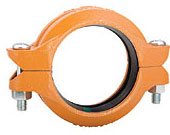
772: Rigid Grooved Coupling
The GRINNELL Figure 772 Rigid Coupling's universal tongue and groove design of the coupling housings ensure trouble free installation. The Figure 772 Coupling provides rigid joint by firmly gripping along the circumference of the pipe grooves. The Figure 772 Coupling is UL Listed for grounding and bonding. This coupling is suitable for bonding systems with a maximum service entrance capacity of 200 amps.
|
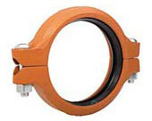 |
705: Flexible Grooved Coupling
The GRINNELL Figure 705 Flexible Coupling allows for angular and linear deflection, thermal expansion and contraction, and misalignments of pipe. It is capable of pressures up to 500 psi (34,5 bar), depending on pipe size and wall thickness. Suitable for use in a variety of applications, the Figure 705 Coupling provides a dependable method of joining pipe.
|
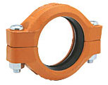 |
707: Heavy-Duty Flexible Grooved Coupling
The GRINNELL Figure 707 Flexible Coupling allows for angular and linear deflection, thermal expansion and contraction, and misalignments of the pipe. It is capable of pressures up to 1000 psi (69,0 bar), depending on pipe size and wall thickness. Suitable for use in a variety of applications, the Figure 707 Coupling provides a dependable method of joining pipe.
|
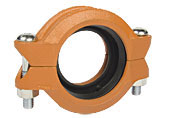 |
716: Reducing Grooved Coupling
The GRINNELL Figure 716 Flexible Reducing Coupling allows for a direct transition between two different pipe sizes, and replaces two couplings and a reducing fitting. It is capable of pressures up to 500 psi (34,5 bar) depending on pipe size and wall thickness. A flexible reducing coupling is not recommended for low-temperature applications.
|
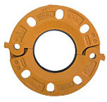 |
71: Grooved Flange Adapter
he GRINNELL Figure 71 Flange Adapter allows a direct transition from flanged components to GRINNELL grooved components. Flange bolt patterns conform to ANSI Class 125 and 150 standards and PN10 and PN16 as indicated.
|
|