 |
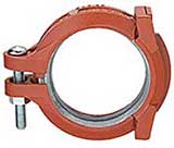
579: Fig. 579 Grooved Rigid Coupling
The GRINNELL G-FIRE Figure 579 Grooved Rigid Couplings provide a rigid joint by firmly gripping along the full circumference of the pipe grooves. Figure 579 couplings are a dependable method of joining pipe and are an economical alternative to welding, threading, or using flanges.
The Figure 579 Coupling is UL & ULC Listed, FM Approved. (Contact TFPP for details)
|
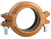 |
577: Light Weight Rigid Coupling
The GRINNELL Figure 577 G-FIRE Rigid Coupling provides a rigid joint by firmly gripping along the circumference of the pipe grooves. The Figure 577 Light WeightRigid Coupling is a proven dependable method of joining pipe and is an economical alternative to welding, threading or using flanges. It is capable of pressures up to 300 psi (20,7 bar) depending on pipe size and wall thickness. The Figure 577 Coupling is UL & ULC Listed, FM, VdS and LPCB Approved.
(Contact TFPP for details)
|
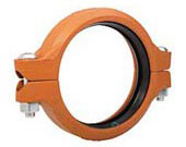 |
705: Flexible Coupling
The GRINNELL Figure 705 Flexible Coupling allows for angular and linear deflection, thermal expansion and contraction, and misalignments of pipe. It is capable of pressures up to 300 psi (20,7 bar), depending on pipe size and wall thickness. Suitable for use in a variety of applications, the Figure 705 Coupling provides a dependable method of joining pipe.
|
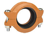 |
716: Reducing Coupling
The GRINNELL Figure 716 Flexible Reducing Coupling allows for a direct transition between two different pipe sizes, and replaces two couplings and a reducing fitting. It is capable of pressures up to 500 psi (34,5 bar) depending on pipe size and wall thickness. A flexible reducing coupling is not recommended for low-temperature applications.
|
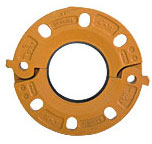 |
71: Grooved Flange Adapter
The GRINNELL Figure 71 Flange Adapter allows a direct transition from flanged components to GRINNELL grooved components. Flange bolt patterns conform to ANSI Class 125 and 150 standards and PN16 as indicated.
|
|

